When the model is solved, there are
Access the Plate Stresses Spreadsheet by
selecting the Results Menu and then selecting Plates ![]() Stresses.
Stresses.
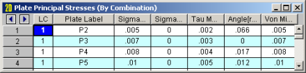
The principal stresses sigma1 (σ1) and sigma2 (σ2) are the maximum and minimum normal stresses on the element at the geometric center of the plate. The Tau Max (tmax) stress is the maximum shear stress. The Angle entry is the angle between the element's local x-axis, and the direction of the σ1 stress (in radians). The Von Mises value is calculated using σ1 and σ2, but not σ3 which isn't available for a surface (plate/shell) element, so this Von Mises stress does not include any transverse shear forces.
The equations are:
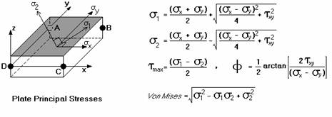
The angle, Φ, is the angle in radians between the maximum normal stress and the local x-axis. The direction of the maximum shear stress, tmax, is ± π/4 radians from the principal stress directions.
The Von Mises stress is a combination of the principal stresses and represents the maximum energy of distortion within the element. This stress can be compared to the tensile yield stress of ductile materials for design purposes. For example, if a steel plate has a tensile yield stress of 36ksi, then a Von Mises stress of 36ksi or higher would indicate yielding of the material at some point in the plate.
For enveloped results the maximum and minimum value at each location is listed. The load combination producing the maximum or minimum is also listed, in the "LC" column.
Note
Access the Plate Forces Spreadsheet by selecting
the Results Menu and then selecting Plates ![]() Forces.
Forces.
![]()
The Plate Forces are listed for each
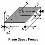
The plane stress forces (Fx , Fy and Fxy) are those forces that occur in the plane of the plate. These forces, which are also called “membrane” forces, are constant through the thickness of the element. Fx and Fy are the normal forces that occur respectively in the direction of the local plate x and y-axes, positive values indicating tension. These forces are reported as a force/unit length. To get the total force on an element, you would need to multiply the given value by the length of the element that is perpendicular to the normal force. For example, looking at the 'Plane Stress Forces' figure, the total Fx force could be obtained by multiplying the given Fx force by the length of side BC (the distance from joint B to joint C).
The Fxy force is the in-plane shear force that occurs along the side of the element. The subscript 'xy' indicates that the shear occurs on the face of the element that is perpendicular to the x-axis and is pointing in the y-direction. Fyx is the complementary shear force, where the subscript 'yx' indicates that the shear occurs on the face of the element that is perpendicular to the y-axis and is pointing in the x-direction. RISA-2D only gives values for Fxy because Fxy and Fyx are numerically equal. The total in-plane shear can be obtained by multiplying the given force value by the length of the element that is parallel to the shear force. For example, when looking at the 'Plane Stress Forces' figure, the total Fxy force which is parallel to the local y-axis could be obtained by multiplying the given Fxy force by the length of side BC.
Note that the
For enveloped results the maximum and minimum value is listed. The load combination producing the maximum or minimum is also listed, in the "LC" column.
Note
Access the Plate Corner Forces Spreadsheet
by selecting the Results Menu and then selecting Plates ![]() Corner Forces.
Corner Forces.
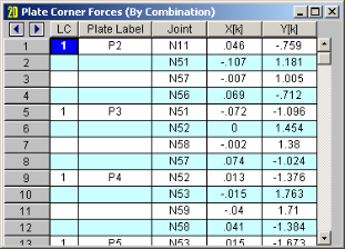
The plate corner forces are the global forces at the corner of each
plate
These are the forces and moments calculated at the corners of the plates,
in the GLOBAL directions. These values are obtained by multiplying
the plate's corner displacements with the global stiffness matrix.
Unlike the local
As an example of how to use these corner forces, you can obtain the total shear at a given level in a shear wall by adding the proper corner forces for the plates at that level. See Plate Modeling Examples to learn how to use the plate corner forces to get shear wall story shears and moments, as well as slab moments and shears.
Note